|
Following World War II, the Soviet Union and the United States gave rocket development a new priority, beginning with careful study of the German V-2. The foremost Soviet experts, Sergei Korolev and Valentin Glushko, were released from arrest to help with this effort. Soon, Korolev was made head of the long-range ballistic missile department of the government research bureau NII-88. Working with German engineers, he began by building a factory to manufacture Russian copies of the V-2. Completed in 1948, this was the R-1, and it proved to be more reliable and accurate than the German original.
Most of the German engineers were returned to their homeland after the R-1 project, and Korolev and Glushko began to design improved missiles and engines. The R-2 was completed in 1949 and had twice the range of the R-1. In 1950, Korolev was granted his own experimental construction bureau, OKB-1, where the future Soviet space program would soon be planned. His R-5 missile was completed in 1953 and had a range of 1200 km, about four times greater than the V-2 and three times greater than Redstone, its American contemporary. The R-5's accuracy was 2 km, ten times that of the V-2. Engine DevelopmentIn the V-2, the Germans had built the largest rocket engine of its time, with 27 tons of thrust. Prior attempts to build such a large engine had resulted in unstable combustion and destructive vibration. They worked around this problem by clustering 18 small combustion chambers to fire into a single large chamber. On the down side, the V-2 engine was heavy, and it was difficult to cool its thick steel walls. This forced the use of low-energy fuels (diluted alcohol) and low combustion-chamber pressures, which greatly reduced its efficiency.For the R-2 and R-5, Glushko designed more powerful engines, based on this paradigm of clustered combustion chambers. In 1947, Korolev proposed the R-3 with a range of 3000 km, but it proved impossible to extend the V-2 engine design to thrusts of 140 tons.

In 1954, work began on the intercontinental missile R-7. To satisfy the engine requirements, Glushko abandoned the V-2 design concept and turned to ideas from pre-war Soviet experiments. In the 1930s and early 1940s, several fundamental engine-design problems had been solved. One of these problems is cooling. First proposed by Tsiolkovsky in the 19th century, regenerative cooling uses incoming fuel circulating around the engine to cool it. An important milestone in that technology was Glushko's ORM-65 (the 65th experimental engine). Tested in 1936, it was probably the first rocket engine that could run indefinitely without melting. Another problem Glushko studied was efficient combustion. Starting in 1931, he experimented with swirling injectors that sprayed fuel and oxidizer in a conical sheet that broke up into tiny droplets. He also built annular mixing injectors that combined the two propellants just before spraying them into the chamber. It is also a good idea to interleave many small fuel and oxidizer injectors on a plate at the far end of the chamber from the exhaust nozzle. This gives the maximum time to mix and burn before exiting the combustion chamber in the exhaust. In the mid 1930s, the ORM-67 was typical of engines that simply sprayed propellants into the center of the chamber. After Glushko's arrest, Leonid Dushkin carried on. In 1938, his RDA-1-150 had 4 fuel and 4 oxidizer swirling injectors clustered on the back side of the chamber, and in 1941, the DA-1-1100 engine had 63 small injectors mounted on a conical plate. The creative engine designer, Alexei Isaev, took over from Dushkin in 1941. His RD-1 had 95 sprayers, but he noticed that its conical injector plate was causing hot channels of gas to form that sometimes burned through the side of the combustion chamber. From 1944-1946 he developed the "modernized" RD-1M, with a flat plate and a checkerboard arrangement of fuel and oxidizer injectors.
One of Isaev's most important inventions was a highly efficient regenerative cooling scheme that would permit high-energy fuel burning at high pressure. The problem is how to built a combustion chamber wall that is heavy enough to contain the forces, but thin enough to be cooled rapidly by flowing fuel. His solution was exemplified by the U-1250, tested in April of 1945. The inner wall was a thin copper sheet, and the outer wall was steel. Between was a corrugated steel sheet that supported the inner wall and allowed cooling fuel to flow past it. The layers were joined by brazing with silver solder. In 1951, Glushko turned to this design for the 7-ton thrust experimental engine, the ED-140. This engine was able to burn liquid oxygen and kerosene at a chamber pressure of 60 atmospheres. By comparison, the V-2 engine burned diluted alcohol at 15 atmospheres. For the proposed R-7, Glushko scaled up this design to produce 68 tons of thrust, with the RD-105 engine. Developed from 1952-1954, problems with combustion instability forced him to abandon the idea of a single giant engine.
In 1954, work began on a more conservative design, with four smaller combustion chambers sharing a common fuel pump system. The chambers were 43 cm in diameter with a 16.85 cm nozzle constriction. Hot gasses reach critical speed at the constriction, and then rebound to super-sonic velocity in the expanding nozzle section. First tested in 1955, the total thrust was 93 tons, with an exhaust velocity of 3020 meters/sec. Exhaust velocity is a measure of a rocket engine's efficiency (also called the specific impulse), and the RD-107 was the most efficient engine in the world at that time. Weighing only 25 percent more than the V-2 engine, it developed over three times as much thrust. The outer wall of the engine was steel, and the inner wall was a durable chromium bronze alloy, 6 mm thick with 5 mm deep channels milled into it to conduct a flow of kerosene for regenerative cooling. The combustion chamber operated at a pressure of 60 atmospheres and a temperature of 3250° C. Kerosene was pumped into a tubular manifold around the bottom of the nozzle, flowed up the sides and into the injector plate at the top, by which time it was typically heated to 210°. The injector plate contained 337 swirling/mixing injectors, with a ring of fuel-only injectors around the outside to provide a fuel-curtain cooling effect. Two variants of the engine were built, the RD-107 with two vernier engines for steering, and the RD-108 with four verniers. The 3.8 ton-thrust verniers were designed by Mikhail Malnikov, a former assistant to Isaev, and these engines were later evolved into small upper stage engines for Lunar and Manned vehicles. The four combustion chambers shared a 3,800 kilowatt steam-powered turbopump. A common drive shaft turned pumps for kerosene, liquid oxygen, hydrogen peroxide (for steam generation), liquid nitrogen (for tank pressurization) and pumps for the vernier engines. A peroxide-powered steam turbine was a German development for the V-2, adapted from the water pumps commonly used in fire engines. The First Intercontinental RocketSoon after Korolev proposed the R-3 missile in 1947, fellow GIRD leader Mikhail Tikhonravov proposed an intercontinental rocket formed by clustering three R-3 rockets, side by side. In his scheme, all three engines would be fueled by the outer two tanks, and after they were exhausted and dropped, the center rocket would continue on its own fuel supply. He called this a feeding packet rocket, because one rocket can feed on the fuel supply of a neighbor.
In 1951, Dmitry Okhotsimsky at the Steklov Institute of Applied Math, carried out a rigorous analysis of how to maximize the range of a rocket by dropping parts of its structure during flight. We generally think of rockets built from sequential stages, but he also considered more general schemes, including Tikhonravov's packet rockets. Okhotsimsky found that the range of the feeding-packet rocket could be greatly increased by making the center stage smaller. However, pumping fuel between stages during flight was a big engineering complication. A simpler scheme was to have the rockets in the packet use only the fuel they carry, a carrying packet. Three identical rockets joined together would not fly any further than a single rocket, but if two of the rockets carry less fuel and are dropped when they empty, performance improves significantly. Because the booster stages weigh less but have equally powerful engines, they contribute increased acceleration during the boosted phase of flight.
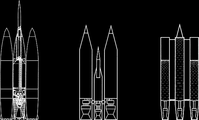
In February 1953, official study began on the problem of an intercontinental missile. The strategic motivation was that NATO nuclear-bomber bases surrounded the USSR. As a deterrent, the USSR could strike Europe, but not the American mainland. To achieve that goal, the R-7 was required to carry a 5-ton thermonuclear warhead to a distance of 8000 km. Okhotsimsky's carrying-packet design was chosen, with a cudgel-shaped central sustainer stage, surrounded by four bullet-shaped strap-on boosters. The 28 meter long sustainer stage, called Block A, was powered by an RD-108 engine with four vernier engines able to pivot 45° to control yaw, pitch and roll. The four strap-on boosters, Blocks B,V,G and D, were 19.6 meters long, each powered by an RD-107 engine with two vernier engines. The combined lift-off thrust was almost 400 tons. An advantage of the packet design was that all five engines could be ignited at sea level, avoiding the complication of designing a second-stage engine that starts at a high altitude in near vacuum. The boosters burn for 115 seconds, then an explosive charge severs straps and they pivot outward and detach. The sustainer stage burns for a total of 299 seconds, reaching a final velocity of 5.8 km/sec.
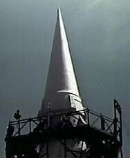
Vladimir Barmin's bureau designed a launch complex for the R-7 in Tyuratam, Kazakhstan, known today as the Baikonur Cosmodrome. A massive ferroconcrete launch pad was built over a 45-meter deep flame pit. The rocket hung over an opening, supported by four retractable trusses attached to load-bearing points at the top of each strap-on booster. On start-up, fuel was allowed to flow by gravity, and the engines were ignited. The inflow of fuel turned the turbine blades, which began to pump hydrogen peroxide into the steam generators. Once steam was produced, the turbo pump powered up to 8300 rpm. The supporting trusses held the rocket down until full take-off thrust was developed, about 10 seconds after ignition. During flight, a special system synchronized the fuel consumption of the four strap-on boosters to keep the rocket's weight in balance. Radio telemetry systems measured over 700 onboard sensors. The Tral system worked by pulse-time modulation (PTM) encoding analog parameters as the time interval between radio pulses. A total of 6000 measurements per second were sent on 48 channels, but channels were often multiplexed to send many sensor readings. Rectangular pads seen on the outside of the sustainer and booster stages covered the Tral antennas, and the electronic gear was held in sealed containers within the fuel tanks. Another system, called RTS-5, was designed to send rapidly-changing data such as engine vibration. It sent 50,000 measurements per second on 8 channels using pulse-duration modulation (PDM). On the rocket, Tral-V reported data on the lateral boosters. Tral-Ts and RTS-5 were mounted in the central booster, Block-A, and reported its state during flight. Receiving stations were constructed along the flight path of the R-7, from Baikonur to the Kamchatka, to receive and record information in case there was a failure. The rocket also contained the radio guildance system, which worked with two RUP stations (radio control points) 250 km on either side of the launch pad. The speed and course of the rocket was measured by trilateration, and commands were sent to stabilize the trajectory and precisely time engine cut-off. A few years later, for the Lunar and planetary rockets and R-7A missile, a single RUP used interferometry to guide the launch vehicles.
In addition to the rocket telemetry, a telemetric warhead was used for flight tests. It contained Tral-G (G for golovnoi chasti, warhead), RTS-5, and transponders for a radar system called Binokl and an interferometric angle measurement system called Irtysh. Sensors measured the thickness of the asbestos/phenolic-resin heat shield, external pressure at the tip, pressure at various points on the sides, internal temperature and pressure, acceleration and angular velocity. The R-7 was originally specified to carry a 3 ton warhead. Later the specification was increased to 5.5 tons, perhaps to carry the RDS-37, a 1.6 megaton bomb developed in 1955. While America set off the first true H-Bomb three years earlier, the Russians focused on practially deliverable "dry bombs" using litihum-6 deuteride instead of liquid hydrogen. The actual R-7 warhead deployed in the early 1960s contained a 5.5 ton thermonuclear bomb yielding 2.9 megatons. After two failed launch attempts in May and July and several launch aborts, the first successful R-7 flight took place on August 21, 1957, from Baikonur to the Kamchatka peninsula. The warhead burned up 10 km above the target range, and Korolev had to make further adjustments to the reentry vehicle and its head shield. A second successful test flight was made on September 7. The next two flights of the R-7, on October 4 and November 3, placed the world's first artificial Earth satellites into orbit. |
 The R-1
 The R-2
 The R-5M
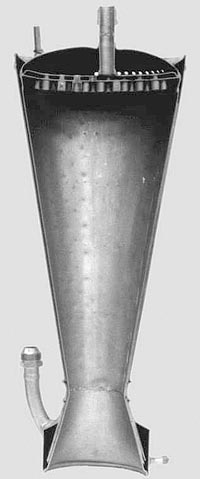 U-1250 Engine
 ED-140 Engine
 RD-105 Engine
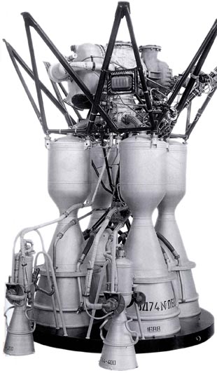 RD-107 Engine
 RD-107 Injector Plate
 The Sustainer and Booster Stages
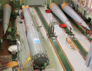
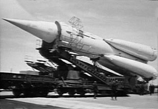 The R-7 ICBM
 R-7 Launch
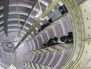 Telemetry Gear Inside Fuel Tank
 R-7 Telemetric Warhead
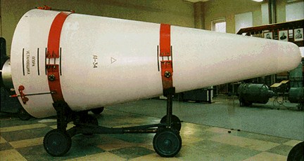 R-7 Thermonuclear Warhead